-
-
Since this is an electrical install, disconnect the battery by removed the negative terminal.
-
Removing the battery provides more room to work.
-
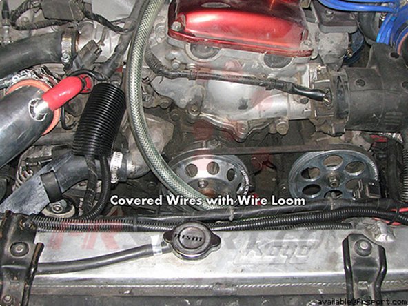
Next, remove stock intake tubing if your car has it. This will allow easier access to the coolant temperature sensor on the intake manifold.
-
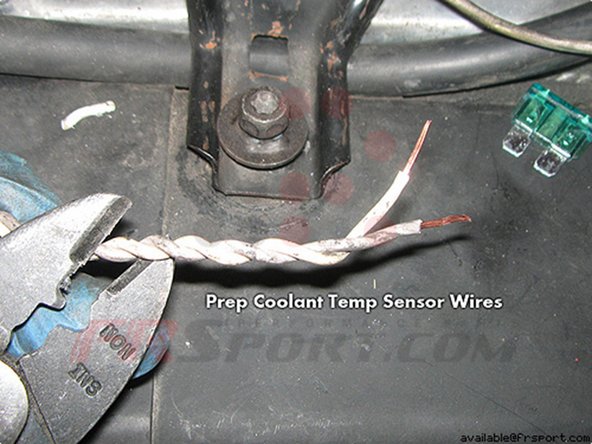
It is recommended to intertwine the white and grey wire from the DIF controller together. (twisted pair wiring)
-
This will help protect against electromagnetic radiation/noise from other components in the engine bay.
-
One way to do this is to insert one end of the wires into a cordless drill; then power the drill until the disred tightness is reached.
-
You can refer to the write-up for the DIF Dual Fan Controller install, which is similar.
-
Image 3 shows what the DIF Dual Electric Fan Controller comes with.
-
-
-
However, note that there are a few key differences, namely in connecting to the fan motors and programming the unit.
-
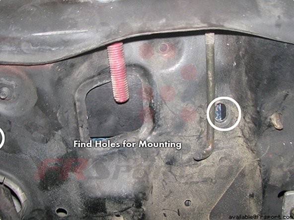
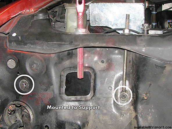
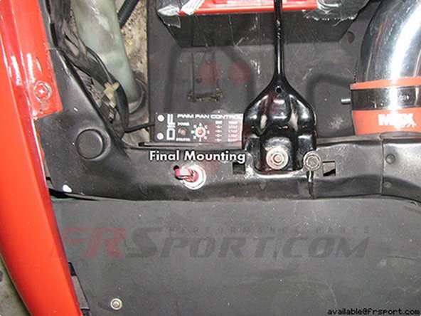
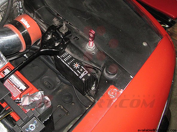
Placement of Fan Controller: I chose to mount the fan controller in front of the battery behind the radiator support.
-
This location is convenient for wiring and re-configuring the DIF controller (if necessary)
-
Feel free to mount it anywhere you find to your liking that is away from heat sources.
-
-
-
A small strip of double-sided tape can be attached to the bottom of the fan controller for simple mounting.
-
It is easier to attached the tape to the fan controller and leave the other side of the tape unpeeled.
-
This will allow moving the DIF controller to a more suitable spot/orientation later during the install.
-
For my install, I chose to modify an L-bracket and mount the controller with screws to the radiator support.
-
-
-
Electric Fans: Connect the positive wires of the fan motors to the battery.
-
Make sure you use the proper AMP fuse for your fan.
-
Connect the negative wires of the fan motors to the two large white negative wires coming from the fan controller.
-
Fan Controller: Connect the large black negative wire of the electric fans to a clean chassis ground area or directly to the negative terminal of the battery.
-
If using a chassis ground, it is recommended to sand the area down to bare metal and using dielectric grease, which will help prevent corrosion and moisture build-up.
-
The large white negative wires of the fan controller should already be connected to the negatives of the fan motors (from above).
-
Image 2: Diagram of wiring for the DIF Dual Fan Controller.
-
-
-
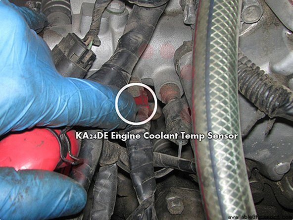
The coolant temp sensor is located on the upper intake manifold near the upper radiator hose inlet.
-
There are two temp sensors in the engine bay - one (1 wire) for the dash, and one (2 wire) for the ECU.
-
The correct one to tap into is the 2-wire ECU sensor. On the KA24DE, it can be identified by a red 2-wire plug held on by a clip.
-
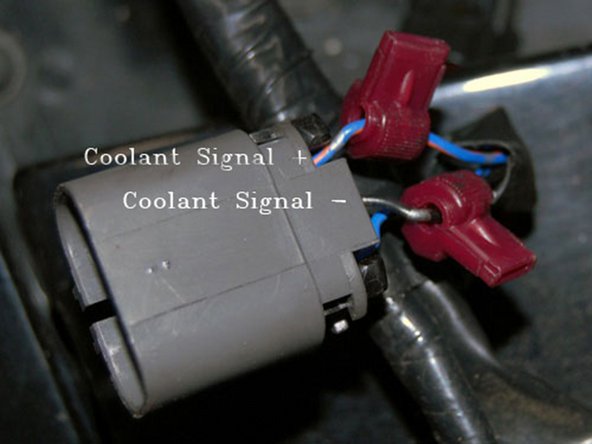
Remove the clip and pull the plug. Once the plug is out, use a razor blade to remove some of the harness cover shielding to allow room for tapping the wires.
-
The blue wire w/tracer is the positive coolant temp. wire. The black wire is the negative coolant temp. wire.
-
Connect these wires to the S+ and S= terminals on the fan controller. After shielding has been removed, you can either tap the wires with t-taps, or strip and solder the connection.
-
-
-
Once the wires are tapped, continuity should be verified with an ohm-meter. Place one prob into the sensor plug and the other onto a metal part of the t-tap.
-
If there is no connection, 0 will be displayed; if there is continuity, a 1 should be displayed.
-
The BA wire for the fan controller should be connected to the battery or other 12v signal.
-
If you don't want the "cool-down" feature, connect the BA wire to an ignition source. The supplied fuse and fuse holder should be used with this wire.
-
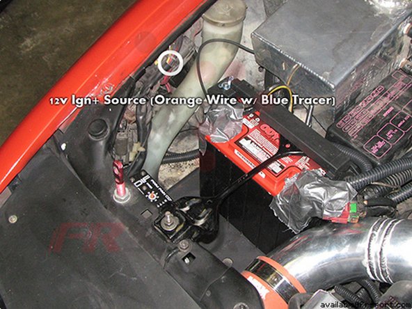
Connect the IGN wire from the fan controller to an ignition source. I chose an orange wire w/a blue tracer located near the battery. I verified this with a voltmeter.
-
-
-
If you want to use the a/c feature (minimal 50% duty cycle fans when a/c is on), you must connect the AC wire to an a/c source.
-
There are a couple of plugs you can tap into near the battery and a/c condenser.
-
For the manual switch, you will need to connect a switch that is connected to a ground and the MA terminal on the fan controller.
-
For all connection points, it is recommended to install heat shrink tubing or at least electrical tape to prevent any shorts in the future.
-
-
-
The fan controller comes unprogrammed. If your fan controller is unprogrammed, it will just show a green light for several seconds, then turn off & repeat the cycle once the car is on.
-
To program the fan controller, you need to move a few wires around to engage "programming mode."
-
Turn the ignition off. Wait 20 seconds.
-
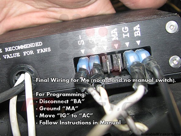
Disconnected BA wire. Disconnect AC wire if you have it.
-
Move IGN wire to AC terminal. Ground the MA wire.
-
Turn the orange knob to the appropriate position (E for Nissan- this will make the fans cycle 4 times when controller is reconnected)
-
Turn the key to the "ON" position.
-
-
-
Reconnect the BA wire.
-
At this point the fan controller should flash the LEDs and pulse the fan(s) to confirm the settings. It will continue to repeat this cycle.
-
After verifying the number of pulses, disconnect the BA wire.
-
Turn the ignition off. Wait 20 seconds.
-
Move the IGN wire back to its original position.
-
Unground/disconnect the MA wire.
-
Reconnect the AC wire. Reconnect the BA wire.
-
When the fan is working properly, the LED should alternate between green and orange. When it is cooling down, it will flash red.
-
-
-
Configuring the DIF Fan Controller: The optimal operating temperature for KA's is approximately 160f to 190f.
-
Since this particular vehicle has a Nismo thermostat installed, which opens thermostat at 143.6F instead of stock 169.7F, I set the fants to turn on at 158F (Letter C) for track days.
-
For stock thermostat, I would probably set it around 170F to 178F, (F to H on the knob).
-
Testing the Fan Controller: Once everything is reinstalled and setup, start the car and allow the engine to warm up. The LED should be alternating between orange and green, as described earlier.
-
Depending on your particular setup, location, and weather, it may take a while before the fans activate.
-
A simpler way to test the fans is to use the manual switch and/or set the adjustment dials to a lower setting, so that the fans turn on earlier.
-
Various LED status video of DIF Fan Controller: Hopefully this video will help some installers recognize the state their fan controller is in.
-
Video of DIF PWM Fan Controller in various states. It covers: Not programmed, programming state, normal operation, cool-down feature.
-